What pin configuration do Noctua fans use?

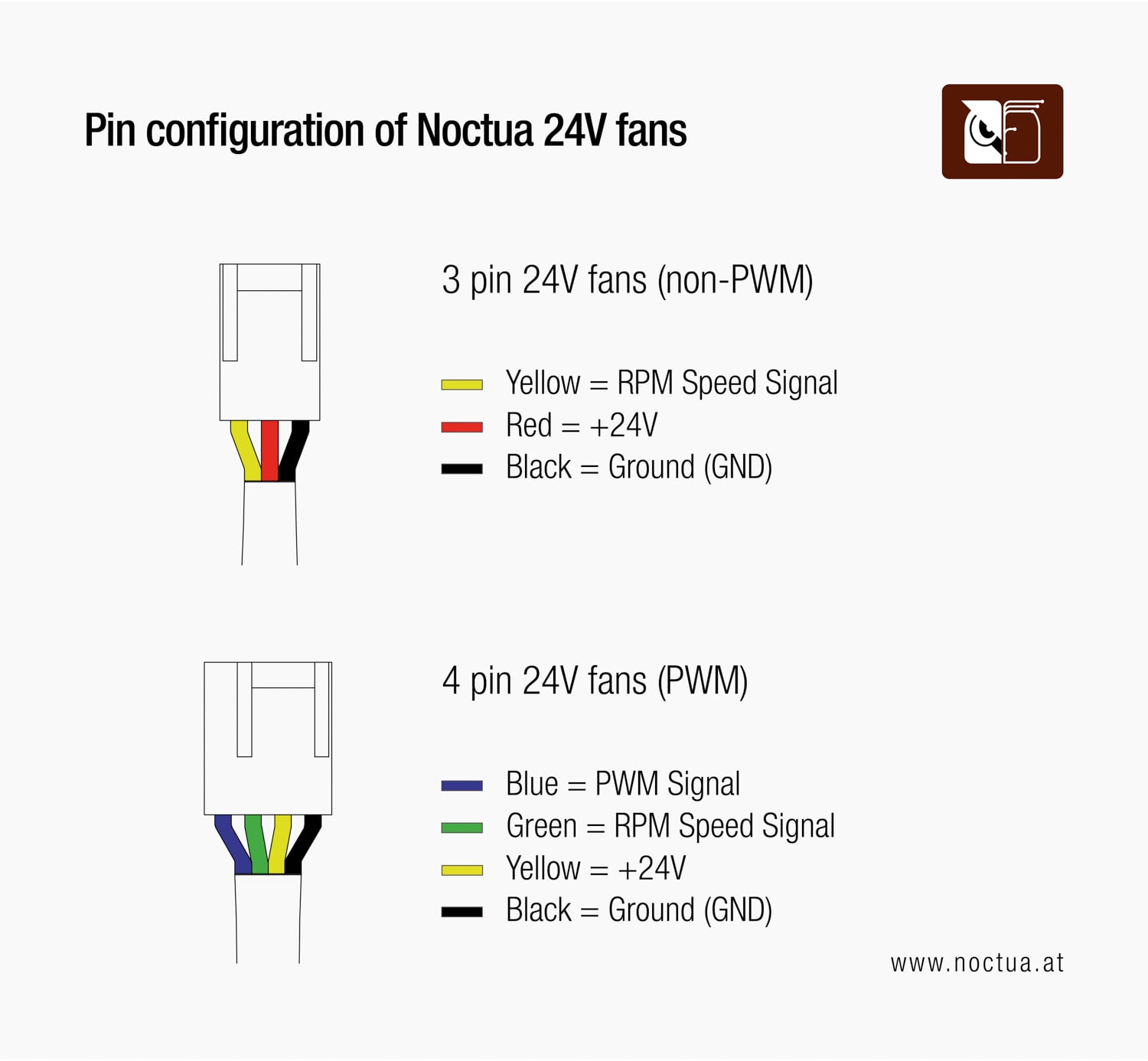
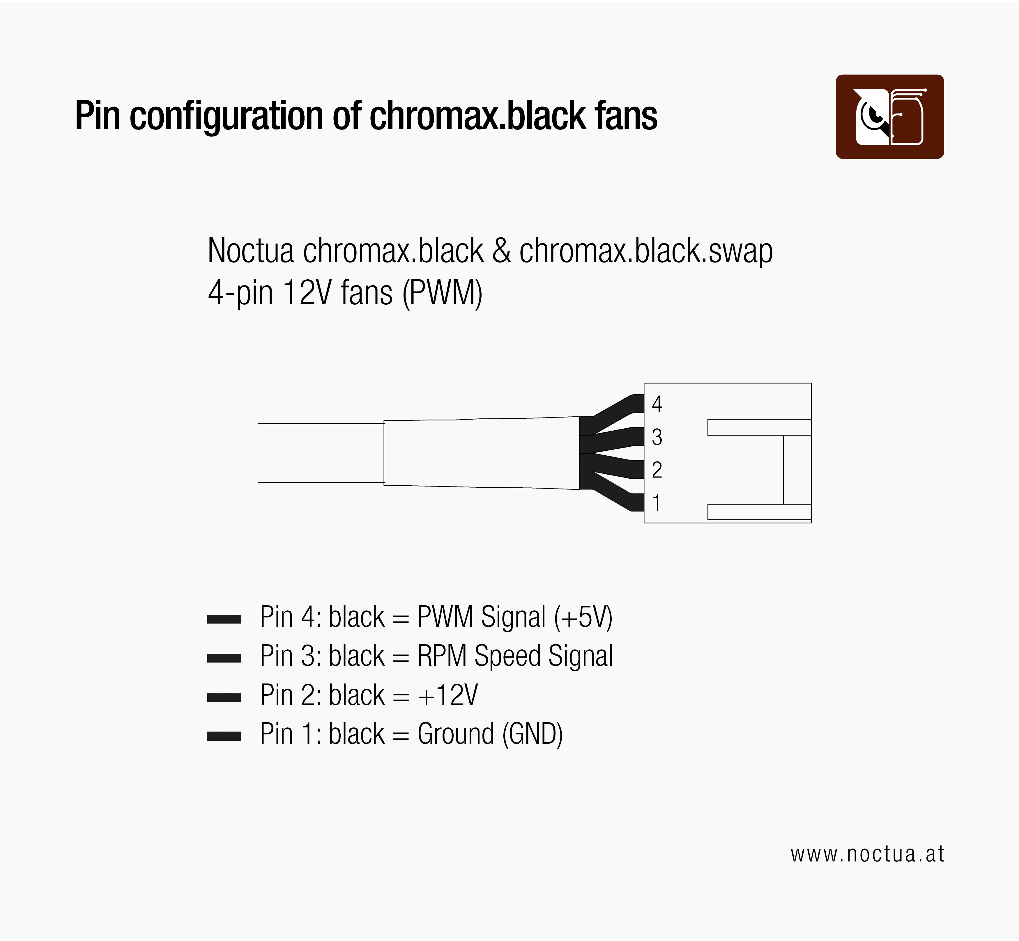
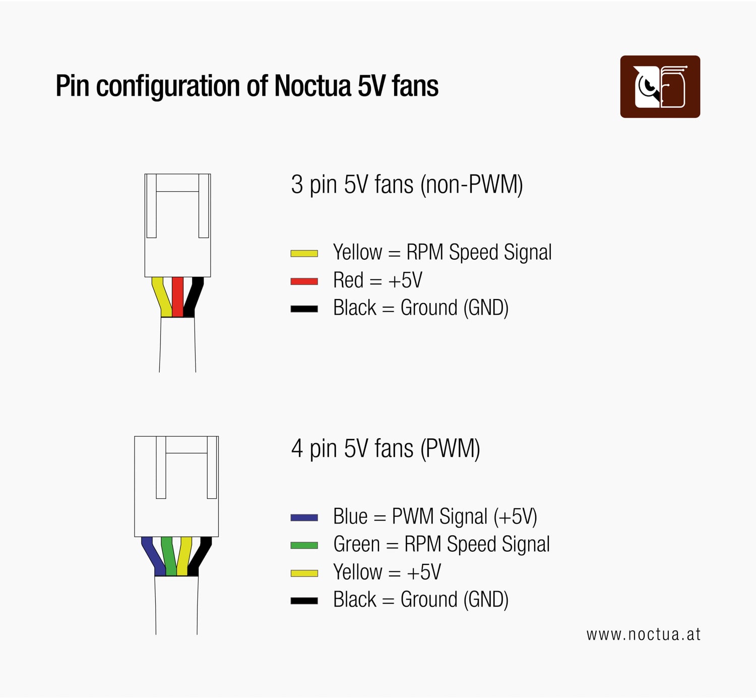
All Noctua 24V, 12V and 5V fans, fan controllers, cables and other accessories such as Low-Noise Adaptors use the same standard pin-assignment that has been specified by Intel and AMD.

Illustration of the pin configuration with the following text.: 3 pin 12V fans (non-PWM): Yellow = RPM Speed Signal, Red = +12V, Black = Ground (GND); 4 pin 12V fans (PWM): Blue = PWM Signal (+5V), Green = RPM Speed Signal; Yellow = +12V, Black = Ground (GND)
Diagram showing the pin configuration for Noctua 24V fans. The 3-pin fan has yellow (RPM speed signal), red (+24V), and black (ground) wires. The 4-pin PWM fan has blue (PWM signal), green (RPM speed signal), yellow (+24V), and black (ground) wires.
Diagram showing the pin configuration for Noctua chromax.black and chromax.black.swap 4-pin 12V PWM fans. All wires are black, with functions distinguished by position: Pin 4 = PWM signal (+5V), Pin 3 = RPM speed signal, Pin 2 = +12V, and Pin 1 = Ground.
Diagram showing the pin configuration for Noctua 5V fans. The 3-pin fan uses yellow (RPM signal), red (+5V), and black (ground) wires. The 4-pin PWM fan uses blue (PWM signal), green (RPM speed signal), yellow (+5V), and black (ground) wires.

If you are looking for information regarding the implementation of PWM (Pulse Width Modulation) speed control in Noctua 4-pin PWM fans, please see our PWM specification white paper